SO
Series Sheet Metal Shears

Product Summary | Key
Features | Hydraulic System
Machine Features | Back
Gauge System | Specifications
Product
Summary
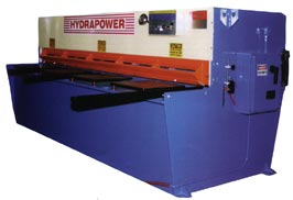
Hydrapower SO-Series Hydraulic Shears: Standard models SO-1000 Series,
from 50"x 10 gauge through 20' x 10 gauge.
Back
to top
_____________________________________
Key Features
Standard Equipment
Push button power back gauge - 36" range
Retracting back gauge bar
Full length low voltage shadow light
High-Carbon High-Chrome 4 edged premium grade knives
4' squaring arm with scale
Comprehensive instruction manual & parts book
Design
Features
Complete hydraulic and electric overload protection
Point of operation safety guards to OSHA requirements
Self-aligning clevis mounted cylinders
Low rake angle to reduce distortion of material
All steel welded and bolted construction
No foundation required
Service
Features
All hydraulic fittings are "O" ring or JIC-37 Flair
-- no pipe threads
All circuits and solenoids independently fused
All the electric wiring is consistently color-coded and terminals
numbered
All commercial components are suppliers standard unmodified shelf
parts
Minimal lubrication required - 4 grease points
Control Features
Convenient knife clearance adjustment & indicators
Convenient stroke length adjustment
Inching controls for added safety
Lockable control selector switch
Foot switch with anti-trip latch
Optional
Equipment
Power operated back gauge extended to 48"
Squaring arm extended to 72", 96" or 120"
Increased throat gap - 12"
Disappearing front stops
Extended front support arms
Additional front support arms
Point
of Operation Guarding
The machine must not be operated without point of operation guarding.
It is the responsibility of the user to insure the machine is operated
safely and has appropriate guards for the type of work being performed.
The manufacturer can not satisfy the guarding requirements for the
many and varied applications these machines can perform. The manufacturer
will assist the purchaser with his selection of guarding and will
offer factory installation of the guarding selected by the purchaser.
Back
to top
_____________________________________
Hydraulic System
The entire hydraulic system is to JIC standards and makes maximum
use of flared fittings, installed with the ultimate in simplicity
and accessibility to servicing the circuit components. The hydraulic
oil tank is designed for operation on 100% duty cycle, with sufficient
oil capacity to dissipate any significant temperature rise above
normal operating levels. All valves are tagged with identification
and pressure settings to simplify servicing.
Back
to top
_____________________________________
Machine Features
Control Panel
The control panel features a lockable mode selector to provide "Off",
"Inching" and "Single Cycle" functions. In the
Off position the machine is completely inactive. The Inching mode
allows the operator to gradually move the top beam down to check
the work prior to taking the cut or to facilitate checking knife
clearance when this may become necessary. This function can also
be used to maintain hold down pressure after taking a cut to allow
the operator to support the material on the table and prevent it
from falling after the hold down's have released.
Knife
Clearance Adjustment
A two-point knife clearance adjustment is provided as
standard equipment. However, because of the basic design and structural
rigidity of these shears, virtually any thickness of stock can be
cut - to the maximum capacity - without adjusting knife clearance.
Being mounted
on eccentric pins or cams, the bearings serve as a simple knife
clearance adjustment. These two bearings are the only two critical
wearing points in the entire machine design. On larger capacity
shears where frequent changes in knife clearance are necessary,
clearances can be altered swiftly and accurately to graduations
shown on a knife clearance indicator.
Stroke Length Adjustment
By means of a simple thumb screw the stroke length may be adjusted
to reduce cycle time and increase productivity on shorter work by
as much as
an additional 80%.
Back
to top
_____________________________________
Front Operated Power Back Gauge
System
This illustration shows the precision gear drives which
are fully sealed and
pre-lubricated. The drive train runs from a 1 HP motor coupled to
the manual fine adjustment hand-wheel and this shaft in turn drives
the self locking reduction gearbox. On both output shafts of this
gearbox are two indexing couplings which provide a simple and convenient
means of adjustment to compensate for any back gauge errors. From
these couplings the drive train runs through two precision gearboxes
which rotate the rolled acme shafts.
Note - A 36"
power back gauge is standard on the SO Series
Back
to top
_____________________________________
|

