DH & DHS Series Press Brakes
Download Video
Product Summary | Key
Features | Levelling System
Controls | Construction
Features | Specifications
Product
Summary
The Hydrapower DH & DHS Series of Press Brakes consists of the following
standard models:
DH & DHS-10000
Series (100 tons) - from 8' through 24'
DH & DHS-13000 Series (130 tons) - from 8' through 24'
DH & DHS-18000
Series (180 tons) - from 8' through 30'
DH & DHS-25000 Series (250 tons) - from 8' through 30'
DH & DHS-33000
Series (330 tons) - from 8' through 36'
DH & DHS-40000 Series (400 tons) - from 8' through 40'
DH & DHS-50000
Series (500 tons) - from 10' through 50'
DH & DHS-60000
Series (600 tons) - from 12' through 50'
DH & DHS-75000 Series (750 tons) - from 14' through 50'
DH & DHS-100000 Series (1000 tons) - from 14' through 50'
DH & DHS-150000 Series (1500 tons) - from 14' through 50'
DH & DHS-200000
Series (2000 tons) - from 14' through 50'
DH & DHS-250000 Series (2500 tons) - from 14' through 50'
DH & DHS-300000 Series (3000 tons) - from 14' through 50'
Tandem available
on all models. Custom orders available on all DH & DHS-Series, with 2
to 8 AXIS CNC controls.
Click
here for sample picture.
Back
to top
_____________________________________
Key
Features
Standard Equipment
Accuracy to within .001" on overall length
Shut height adjustable while pressing
Tilt adjustment providing .050"/REV to +/- 1"
Tonnage control and indicator
Rigid deep section bed and ram
All steel, welded & interlocked construction
Side frames capable of full off center load
Complete overload protection
Non-metallic wear resistant slides with zero running clearance
Universal gauges
Four speed system; Fast approach/Slow pressing/Slow withdrawal/Fast
return
Full tonnage through entire stroke
Die adjusting set screws
Centerline loading on side frames and tool centerline
Self-aligning clevis mounted cylinders with hard chrome piston rods
Pendant or Pedestal Controls (Customer Choice)
Portable footswitch control with safety guards
Automatic lubrication system
Optional
Equipment
Power operated back gauge with digital read-out
Programmable power back gauge (DELEM DAC-250)
CNC bend angle and back gauge control systems (2 to 6 AXIS) with
graphics
Increased throat gap
Increased die space
Increased stroke
Increased cycle speeds
Horn extension for bed and ram
Provision for Tandem operation
Machine for angle brackets
Permanently flanged bed and ram
Pendant or pedestal control stations
Tandem foot switch controls
Flush floor bed style where feasible
Digital reading tilt adjustment
Safety light curtain
Point of Operation Guarding
The machine must not be operated without point of operation guarding.
It is the responsibility of the user to insure the machine is operated
safely and has appropriate guards for the type of work being performed.
The manufacturer can not satisfy the guarding requirements for the
many and varied applications these machines can perform. The manufacturer
will assist the purchaser with his selection of guarding and will
offer factory installation of the guarding selected by the purchaser.
Back
to top
_____________________________________
Unique and Efficient Levelling
System
The precision leveling system is the simplest and most efficient
ever to be used on press brakes. Like many of the notable brands
we use the thin tape as the mechanical method of transmitting the
out-of-parallel tendency of the ram but this is where the similarity
ends. On other brands the control device attached to the end of
the tape causes a valve on the hydraulic system to dump oil or impose
a back pressure to bring about correction of the out-of-level condition.
Both these actions waste horsepower which is converted directly
to heat energy in the hydraulic oil.
The Leveling
Sensor on the Hydrapower Press Brake mechanically amplifies the
movement of the tape caused by any out-of parallel tendency. This
magnified movement will actuate one of the two micro-switches (Advance
or Retard) if the ram becomes out of parallel by as little as .0005.
Contact with the limit switch now activates a miniature solenoid
which decreases the volume to the slave circuit. The very small
changes in displacement take place smoothly without impulses or
shock to the hydraulic system. The leveling sensor needs no lubrication
and has no wear-affected parts. The two micro-switches which are
actuated by the leveling sensor are capable of millions of cycles
and are accompanied by two "back up" units to ensure the
system is fail safe even when the stager micro-switches malfunction
due to age. Replacement of these units is readily accessible and
simple to perform when the need should arise.
Robust
Deep Section Bed and Ram
The bed and ram dimensions are designed to provide the maximum rigidity
with a reasonable amount of weight. The depth of these members is
the most important dimension. Some long bed models require a cavity
in the floor to accommodate the bed but this can be avoided by substantially
increasing the width of the bed with a resultant increase in weight
for the same rigidity.
Extra
Long Slides
To ensure longer life and greater accuracy the machines are equipped
with very long slides. When the housings are being machined for
the slides, a reference level surface is also machined at the same
time to enable the slides to be accurately realigned when the press
brake is being installed.
The slides require
no lubrication and run with zero clearance to insure front to back
precision within .001".
Front
Operated Back Gauges
To facilitate fast set ups, front operated back gauging may be added.
For further convenience a push button, power driven back gauge is
also available. Either form of these options includes a digital
reading position indicator.
Portable
Footswitch
The Portable Footswitch has anti-trip protection to prevent accidental
actuation. The footswitch is attached to a reinforced flexible cable
which is resistant to abrasion, oil and being crushed.
Note: When the
foot switch is released, all downward motion will immediately cease.
Back
to top
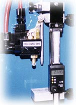
Controls
Stroke
Control Data
- High Speed
Control Rod can be readily raised or lowered to provide high speed
in the approach and return directions.
- Top of Stroke
Cam adjusts up and down the bar to allow swift changes in open
height.
- Tonnage Control
Indicator provides adjustment of tonnage capacity to protect tooling
against overload.
- Bottom of
Stroke Digital Read-Out adjusts shut height for precise control
of bend angle. Bottom of stroke is referenced to the dies and
provides constant position regardless of tonnage changes.
Stroke
Adjustment
Standard
models have a digital reading stroke adjustment for precise control
of the shut height position. Optional six station turret stops facilitate
forming up to six different angles in sequence. The top of the stroke
or "open height" position may be set anywhere throughout
the stroke to reduce cycle time and speed up production.
Standard
Operating Controls
- Lockable
Mode Selector located on the main panel "Off" - "Inch"
- "Single Cycle" functions.
- Lockable
"Hand" - "Foot" Selector on main panel allows
supervisor to limit operation to either two hand station or foot
switch.
- "Inch
Up" buttons located on main panel and on ram operators station
provide "Up" functions at any point and these override
the top of stroke switch cam.
- Motor Start/Stop
Buttons are located on main panel.
Tonnage Indicator and Control are located on main panel and provide
additional overload limits.
- Two Hand
Station houses the "Two Inch Down" buttons and "Inch
Up" button.
Back
to top
_____________________________________
Construction Features
The frame and all attachments are fabricated from high-quality
steel to produce a virtually indestructible assembly.
The hydraulic
cylinders are connected to the RAM with hardened, self aligning,
spherical thrust bearings which provide exceptionally long service
without the need for lubrication. Deflections and overloads in the
frame and housing have no effect on cylinder and slide alignment.
The hydraulic
system involves less valves than most other press brakes and reflects
the simplicity and convenience of service which we design into the
machine.
The electric
system is supplied to UL and CSA requirements and it is designed
for ease of service. A weather-proof panel contains operating push
buttons and switches. A safety disconnect is interlocked in the
panel door which contains the motor starters, overloads, and control
transformer. It also includes the terminal strip with an individual
fuse for each solenoid function.
Back
to top
_____________________________________
|